< Driving and Coupled wheels >
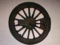
Driving and coupled wheels are made of cast
iron. Before turning, the castings are cleaned
(removed sand and burr) and painted.
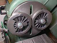
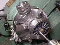
In this setting you can cut the balance weight
without disturbing the bosses.
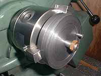
Same as the pony wheels, I prepared a special
faceplate with a spigot to machine tread
and flange of the wheels. Once you chuck
and true up the jig, never release it until
you finish all of the turning operation.
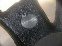
Normally the holes for crankpins are bored
in a bench drill with a positioning jig,
and reamed by hand. But I bored and reamed
the holes in the lathe. Note the jig which
I used for wheel turning is used again to
ensure positioning.
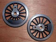
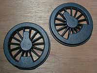
Finished wheels.
The crankpins are glued to the wheels with
Loctite #603. I added lock-pins to the driving
crankpins so as to prevent the crankpins
from turning.
The axles are also glued to the wheels. This
"quartering" is done in the lathe.
The left side crankpin is hold horizontally
on a suitable length of round bar, while
the right side crankpin is hold vertically
along a square gauge. Don't forget to insert
axleboxes and eccentrics to the axles before
the quartering.
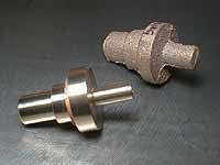
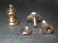
Pony truck spring plungers and housings are
provided as integrated castings. Don't saw
the two parts off at first. You can chuck
one end in the three jaws when cutting another
end.
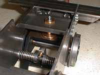
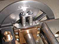
I added a simple side-control function to
the pony trucks. Along a round stretcher,
two sleeves with coil springs push the hook
of the pony truck from both sides. Side-control
force is adjusted around 1/3 of the pony
axle weight.
Axlebox is supported by coil springs. This
typical manner has, I think, two disadvantages.
The axle weight doesn't push but pulls the
pins. It means the thread in the axlebox
has to resist the axle weight. Additionally,
the pins are close to the rails and easily
damaged once the loco derails. In the case
of "Rob Roy", in which the coil
springs are located onto the axleboxes, you
are free from such problems in exchange for
adjustability.
Coil springs are coiled from stainless steel
drawn wire, around a mandrel chucked in the
three jaws. To obtain desired size of coil
springs,
1) Diameter of the mandrel should be 10%
smaller than the desired inner diameter of
the coil.
2) Number of turning should be 10% more than
the desired number.
3) "Pitch" of coiling should be
10% shorter than the desired pitch.
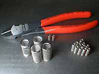
You have to use "piano-wire cutter"
to cut the drawn wire. If you use a general
cutter here, it will be spoiled immediately.
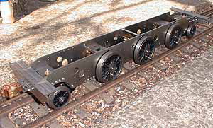
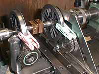
The erected chassis on a club layout.
| TOP | BACK | NEXT |