< Boiler Cleadings 1>
To efficiently fabricate the boiler cleadings, it was decided to remove the smokebox and boiler from the chassis and bring them into the workshop. Beforehand, smokebox stays were fabricated to support the smokebox from the front buffer casting.
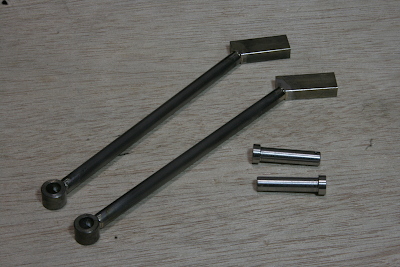
The smokebox stays, located on the underside of the front floor panel, were made from steel round bars and flat bars, assembled with silver soldering. The lower parts were fixed with pins made from stainless steel round bars.
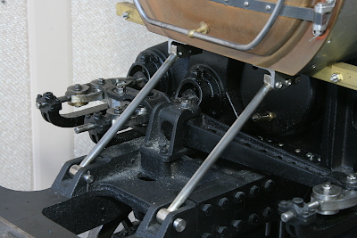
Installed between the front buffer casting and the smokebox. It becomes entirely invisible from above once the front floor panel is attached.
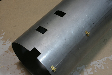
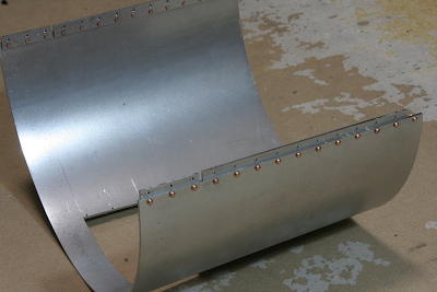
The boiler cover was made from 1.6mm steel sheet. Thinner materials could suffice, but thicker material was deliberately chosen to accommodate tapping and attaching components. Due to limitations with my bending roll, outsourcing was done for the bending process. While actual boiler cleadings are divided into multiple sections with boiler bands, for the model, the front straight portion was kept as one piece, the tapered portion near the safety valve was divided into upper and lower sections, and the firebox portion was bent into a U-shape. Subsequently, these are referred to as the first, second, and third cleadings.
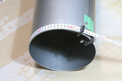
On the first cleading, scribe guide lines divided into quarters in the circumferential direction. Metal tape measures were tightly wound around the end of the body, clamped, marked into quarters, then scribed with a cutter using a metal ruler as a guide. Similarly, center lines were scribed on the second and third cleadings. Attachment positions for parts on the boiler cleadings were determined based on these scribed lines.
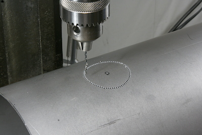
A hole for the steam dome was opened on the first cover, creating a circular pattern with a 2mm drill, then cut out with a fret saw and finished with a half-round file.
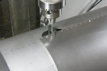
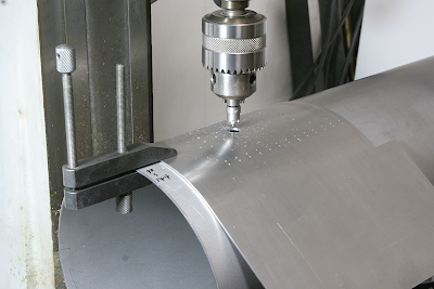
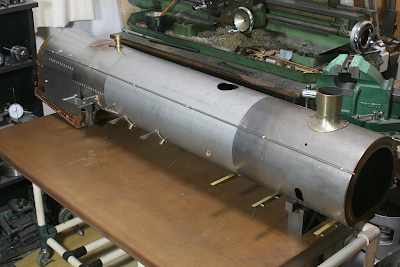
Subsequent holes on the second and third cleadings were drilled on the first cleading as a stage. Note a prop supporting the first cleading against drilling pressure.
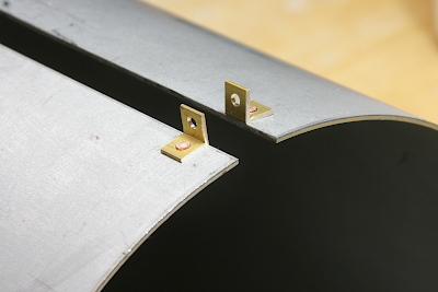
Brass angle lug terminals for squeezing the first cleading around the boiler were attached to the lower part of the cleading. The lug terminals were fixed with copper rivets and reinforced with high-temperature soft solder.
Holes for the running board supports and the power reverser were opened on the lower front half of the first cover. These were also cut out rectangle patterns with a drill and finished with a file.
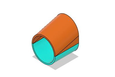
The diagram shows the emphasized image of the second cleading. Only the top ridge tilts, while the sides and bottom are straight. The cleading is divided into the upper and lower parts. The upper is made by cutting diagonally from a dome shape, while the lower is a regular semicircle.
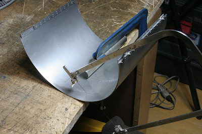
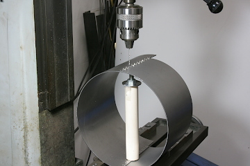
The part where the whistle is attached on the upper half is cut out, and a flat plate is inserted. It was cut out with a fret saw as shown in the photo. To prevent deformation of the plate, it was fixed to the table using a round bar.
The flat plate was made from a brass sheet. Gaps between the plate and the round top were covered with separate side plates. These were fixed with copper rivets and reinforced with flowing high-temperature soft solder. The holes for the safety valves in front were cut with a 25mm hole saw.
Originally, the second cover was intended to be assembled with screws, but for visual reasons, it was fixed with copper rivets. A connecting band was inserted at the back. This band is utilized from curved material cut from the lower end of the first cleading.
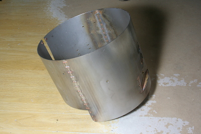
For assembly, the lower part is cut into the left and right parts and assembled with lug terminals similar to the first cleading. The parts connected with copper rivets on the sides were reinforced with high- temperature soft solder.
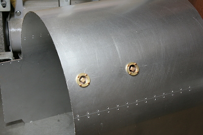
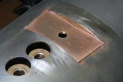
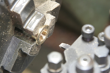
On the third cleading, washout plugs were attached. The machining method is as follows. Incidentally, the row of drill holes below the washout plugs are for planting dummy rivets.
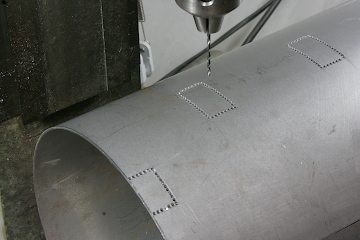
The holes for the washout plugs were opened with a hole saw, utilizing the first cover as a base.
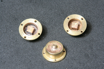
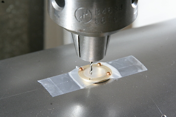
The main bodies of the washout bushes were turned from a brass round bar. The circular holes were opened as usual, clamping with a three-jaw on a milling table and drilling at calculated coordinates.
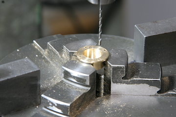
The central plug was made from brass square bars. The lower end was turned round, threaded, then silver-soldered into the main bush. The fixing holes were copied from the bush, then fixed with copper rivets.
Assembly thereafter utilized an old chest's tabletop as a flat surface. The boiler cover and smokebox were attached to the boiler, followed by brackets and handrails. Detailed fabrication will be reported next time.