< Valve Gear 4 >
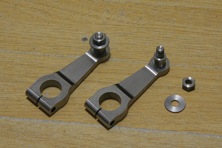
The next parts are return cranks. Hole for the crank pin has a slit in order to fasten the crank pin with a screw. Bottom of the big end is rounded along the screw hole. Pin at the small end is g;lued in the body by Loctite 648.
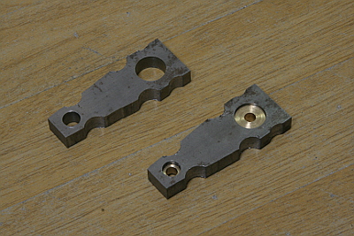
They are made from steel flat bar. Drill and ream holes, cut inner radius with end mill and saw off excess part. The brass bushes are for adjusting diameter for pins on the jig.
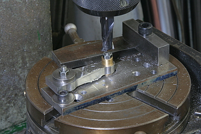
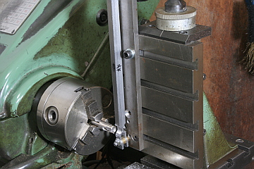
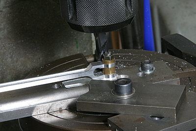
Small head is cut on the rotary table.
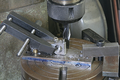
Cut bottom round face. I prepared small angle on the rotary table and fixed the return crank to the angle.
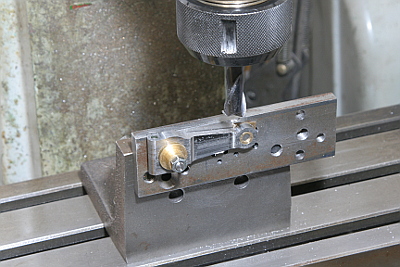
Finally middle part of the side face is cut to a thickness.
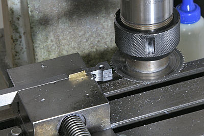
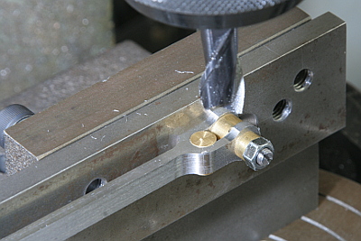
The photo shows how to fix the return crank angle. I utilized two brass bars of specified length. While a bar holds the crank pin truly horizontal, another bar sets the crank pin in desired angle.
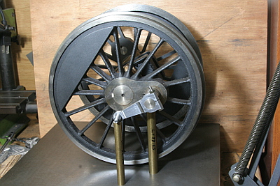
Wheelbase of the eccentric rod is determined from job. I prepared wheelbase gauge made from two flat bars connected by slotted holes and screws. The wheelbase is determined so that the expansion link becomes truly neutral when the crank pin is at both front and back dead center. The expansion link neutral is a position that gives no movement of valve crosshead at any radius rod position. If there is difference between front and back dead center, it shows the above determined return crank angle is bad.
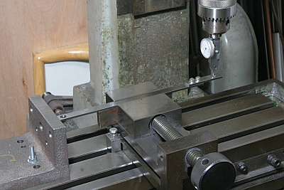
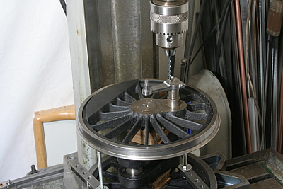
The wheelbases can be converted into numerical values as follows. Using milling stage, align each hole to the milling head by DTI and read x and y origins, then calculate distance from the origins. I found 0.6mm difference of the wheelbase between right side and left side expansion links.
In order to fix return crank angle, a key is inserted between crank pin and return crank hole. Full size C53 has rectangle key. But I adopted simple round key. Drill a hole between them and knock a pin into the hole.
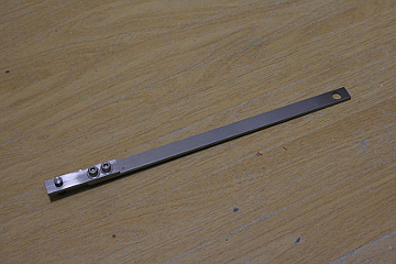
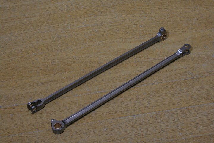
The last job is eccentric rod. Machining procedure is almost the same as radius rod except flute cutting. Wheelbase of each rod is reproduced by the milling stage.
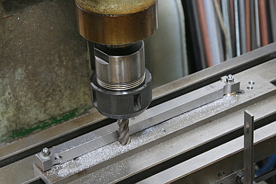
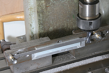
Same as radius rod, almost of the volume has to be removed. The photo shows cutting excess thickness of the rod by roughing end mill.
The front fork end is cut. Drill through bottom cross hole, open the fork by circular saw and finished by end mill.
The middle thin part is finished. First the radiuses at both ends are cut by end mill, then the side face is milled.
The flute is cut with the same setup.
Cutting each head in the rotary table.
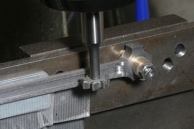
Shoulder of the fork end is also cut in the rotary table. The cutting radius and the bottom cross hole are concentric. The jig is set up as follows.
- Align rotary table center to the milling head center.
- Insert a brass bar with scribed center into the fork cross hole and fix the job in the jig.
- Mount the jig on the rotary table, align the brass bar center to the milling head center and bolt down the jig.
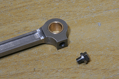
Finally a gunmetal bush is push into the back hole and a dummy oil cap made from steel bar is screwed into the back head.
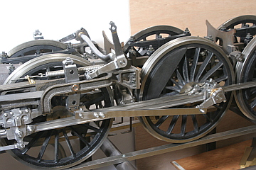
The Walschearts valve gear is completed. Still the Gresley conjugated valve gear is remained.