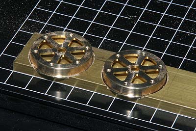
< Snifting Valves >
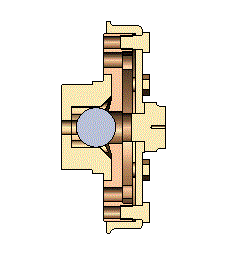 Snifting valves of JNR C53 exist at both sides of the cylinder valve chests.
The full scale snifting valve has disk valve but I adopted stainless steel
ball valve as same as typical model steam loco. The picture shows section
of the valve system. The valve chamber holds the ball horizontally and
also limits the stroke of the ball. The valve seat is bolted down onto
the cylinder's flange. The valve cover is bolted onto the valve seat.
Snifting valves of JNR C53 exist at both sides of the cylinder valve chests.
The full scale snifting valve has disk valve but I adopted stainless steel
ball valve as same as typical model steam loco. The picture shows section
of the valve system. The valve chamber holds the ball horizontally and
also limits the stroke of the ball. The valve seat is bolted down onto
the cylinder's flange. The valve cover is bolted onto the valve seat.
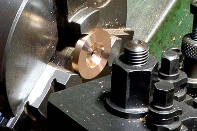
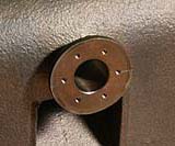
The valve seat is made from phosphor bronze round bar. The center hole is finished with boring tool and the seat is cut at 75 degree taper.
Holes for screw are opened in the rotary table.
The cover has windows of "orange slice" shapes. Usual process is drilling every corner, cutting out with fret saw and filing. But it sounds terrible for me. Such thin brass material can be cut by Modela.

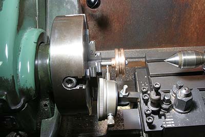
First, the cover body is turned in the lathe.
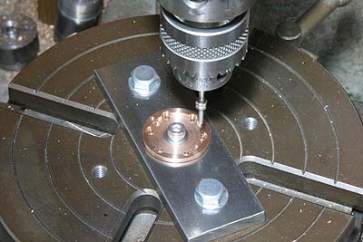
A brass flat bar is set on the stage of Modela with mounting tape. And then, grooved ring for alignment is cut with small mill.
The valve cover rim is glued into the groove with strong epoxy adhesive. Then Modela drills holes for screws with center drill, and cuts the windows with 2mm end mill. After that, the adhesive is removed with propane gas torch.
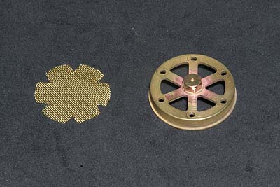
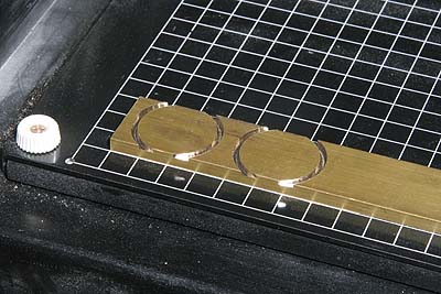
The cover center bolt is made from brass hexagonal bar and silver soldered onto the cover. The mesh screen is made from brass mesh sheet. Note V-shape notch to clear screws.
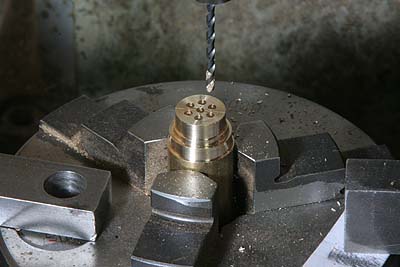
Next is the valve chest. It has seven holes for steam path. Before parting
off in the lathe, these holes are drilled in the milling machine.
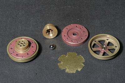
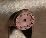
The photo shows valve assembly and every part. Before assembly, valve 'seating' is done with a precise steel ball and a small hammer.
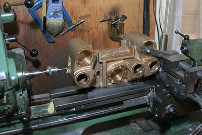
So as to drill and tap screw holes in the cylinder block flange, lathe center height over stage is not enough for the operation. So I put the cylinder block on the lathe bed through suitable packing and I coupled the cylinder block with the lathe table, as the photo shows. As the drilling diameter is only 1.6mm, I could obtain enough rigidity with it.
Following photos show process of the assembly. The cover is fixed with very tiny brass bolt (1.7mm) that is hard to get nowadays. I spent my little stock!
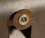
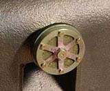
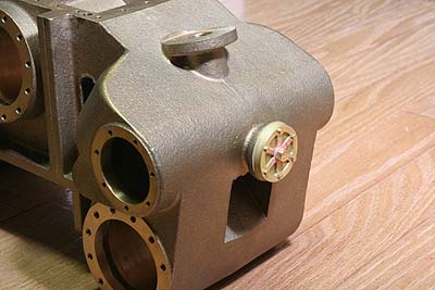
Finally each side of the cylinder block will be covered with metal sheet. But the shifting valve will be exposed through round hole of the sheet.
Some time ago, Kozo Hiraoka checked my report and suggested me to decrease
pressure of the piston o-ring. I had also felt the piston motion was too
tight. So I decrease the o-ring squeeze from 0.4mm to 0.2mm with the same
setup as I reported in August. Finally the piston motion became very smooth.