< Brake System 1 >
The brake system of C53 locomotive is peculiar.
Leverage connection spreads vertically instead
of horizontally. Both 1st and 2nd brake hangers
are between 1st and 2nd wheels. On the other
hand, there is no space between 2nd and 3rd
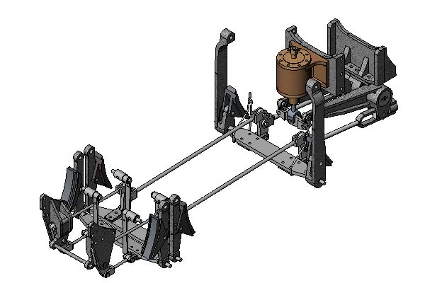
wheels. So the 3rd brake hangers cross over
the 2nd and 3rd wheels from outside. The
following CG shows modeled brake system without
wheels and main frames.
I intend to employ working steam brake for
the engine, in addition to a typical hand
or foot brake for the tender. In order to
prevent wear of wheels, the brake shoes are
made of aluminum castings, and section of
the brake shoes traces wheel contour as same
as the prototype. In this case, the brake
shoes must follow the wheels' side play.
So the connecting pins in the hanger must
be enough loose to allow the hanger to tilt
in side direction.
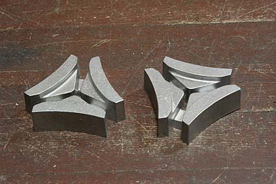
I started from the brake shoes. With a chemical
wood pattern made by MODELA, I ordered aluminum
castings of 12 brake shoes including a whole
spare set. Incidentally, if the wheels are
not large, the brake shoes castings can be
arranged in a diameter of the wheel, then
the whole jobs can be turned in the lathe
at a time.
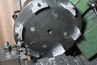
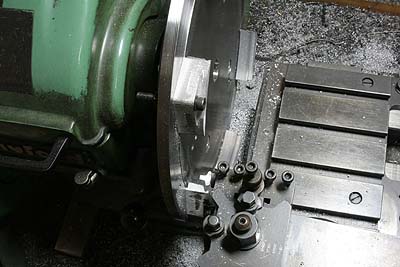
I utilized the large face plate for wheel
cutting again. After finishing top and bottom
face in three-jaw, the castings are separated
and bolted onto the face plate in a diameter
of the driving wheel. I start cutting with
arc steps in top face of the castings.
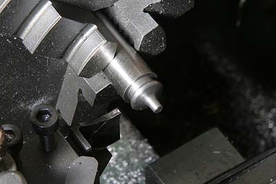
Here I made a tool for cutting the flange
shape of the tire contour. A high carbon
steel rod is turned in a desired shape, cut
half round by end mill, hardened, tempered
and oil-stoned.
The castings are reversed and bolted onto
the plate. The straight tread face is taper-cut
by a boring tool. After that the flange shape
is cut by the made tool.
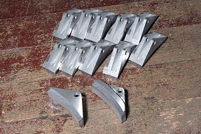
The brake shoes are finished by slitting
with end mill. A number of parts could be
finished in comparative short time, because
the aluminum casting is very soft.
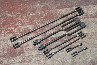
Next I made all kinds of brake rods with
forked ends and eye bolts, except the last
pair with U-shape castings. Large brake arms
will be connected to the castings. Note the
rod diameters are different in one another
(1st < 2nd < 3rd), because the braking
force is accumulated by the leverage.
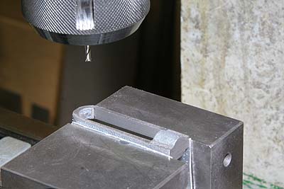
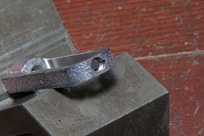
The forked end is made from laser-cut flat
plate, bended with the jig that I used for
the wheel spring bracket. The photos show
the jig without and with the job. After bending,
holes for connection are opened.
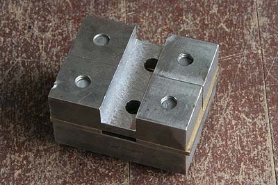
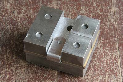
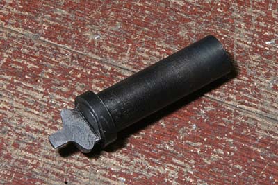
The photo shows cutting the U-shape cast
iron. After finishing the thickness, inner
pocket is cleaned by end mill. A die block
will fit along the pocket and be connected
to the large brake arm.
All of forked ends and the others are silver
soldered onto ends of the rods. So as to
hold the job firmly during the soldering,
the rods and holes are threaded. Note a fine
groove is cut across the thread. It helps
silver solder to flow through the thread.
Care must be taken to silver solder cast
iron, for its repelling surface and heat
denaturation.
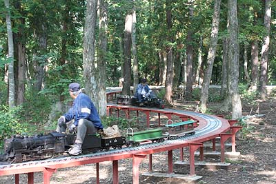
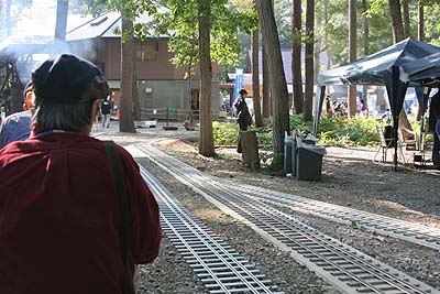
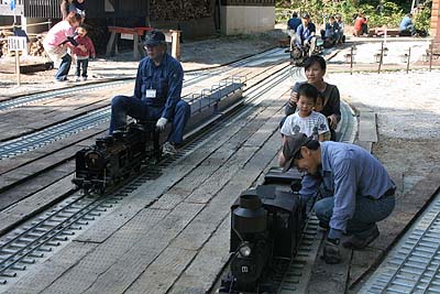
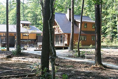
Hakuba Mini Train Park
In October I visited new 5 & 7 1/2 inch
dual gauge track layout "Hakuba Mini
Train Park". Hakuba is a famous skiing
ground in Nagano. The layout was constructed
cutting a path through the thick forest.
It provides unique and nice feeling like
a logging railway. Total track length is
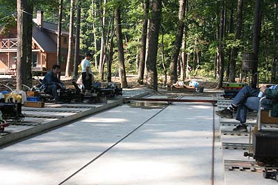
around 1000 meters. The layout has a station
with four platforms, steam shed and traverser.
The last photo shows a devise for connection
between offset-reversed tracks.
![]()