< Driving Wheel Assembly 2 >
The cranked axle for the second driving wheel
is made of cast iron plates and silver steel
shafts. The axle shaft already had been finished,
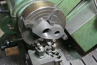
so I tackled with the castings. First, back
face and axle bore are finished in four-jaw.
As the photo shows, I prepared a jig on the
face plate, so as to finish the crank hole
in true distance from the axle hole. The
stack of gears is balance weight for turning.
The shafts are glued into the castings with
Loctite. Both ends of the crank shaft are
thinned in diameter, in order to determine
distance between the castings. Also a small
pin on the axle positions the castings truly
midpoint of the axle.
In case of Gresley derived motion, three
crank axles have to be quartered exactly.
Because the inner valve motion is a composition
of two outer motions. I employed following
procedure.
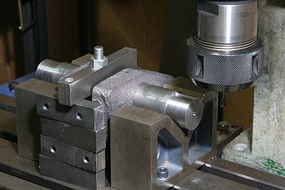
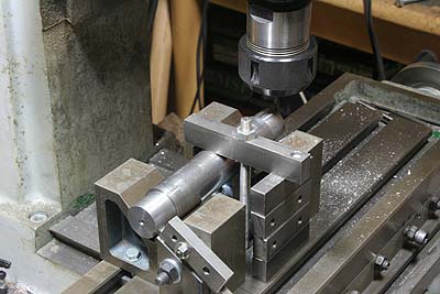
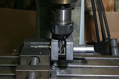
Pair of V-blocks is bolted down on the milling
stage parallel. The cranked axle is mounted
on it and the crank angle is set by a brass
post of true height. The axle is clamped
firmly and the key groove is cut by end mill.
In the first photo, the post is hidden behind
the clamping blank. After that, the opposite
key groove is cut in the same manner with
a different post. It means the each key groove
is angled from the inner crank axle independently.
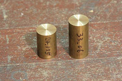
The second photo shows the brass posts.
To tell the truth, I had made an irreparable
mistake here. I will show it next month.
If you look at above photos carefully, you
may aware of the mistake.
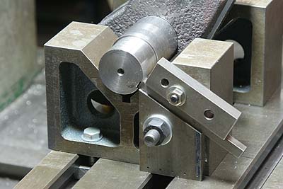
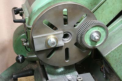
Before dismantle the setup, I copied the
quartering result (angle between two grooves)
down to a jig as the photo. The jig consists
of 30 degree slope base, sliding square bar
and upper guide plate. The tip of square
bar is cut to a push-fit to the groove. The
upper guide plate pushes the square bar hard.
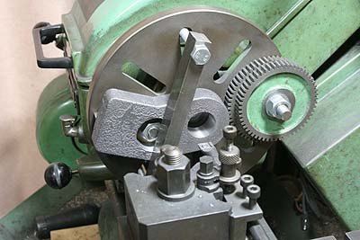
First and third driving axles are finished
with the jig. After cutting a groove, the
axle is reversed and its angle is fixed by
the jig. And then the opposite groove is
cut.

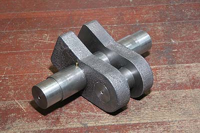
So as to secure the shafts of the cranked
axle firmly, I drove 4mm spring pins in every
connections.
Finally, middle part of the axle is cut by
band saw, and finished by end mill.
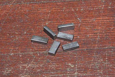
The rectangle keys were made from square
steel bar. The length is about half of the
wheel thickness. Key's thickness is 0.1mm
shorter than the height of key hole between
wheel and axle. Key's width is first cut
to 0.1mm larger than the key hole width,
and then finished to press-fit to the hole
with fine files. All keys are temporary hammered
into the key holes and checked there is no
play.
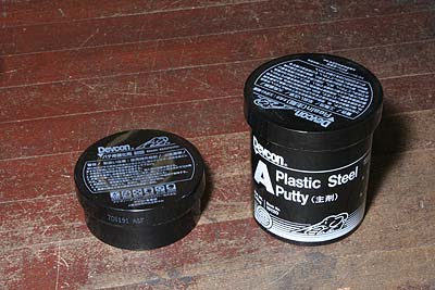
There are blow-holes in the wheel castings,
particularly at the root of spokes. I repaired
them by Devcon plastic steel putty. Before
it, the wheels are cleaned and degreased
by paint thinner and rinsed by acetone.
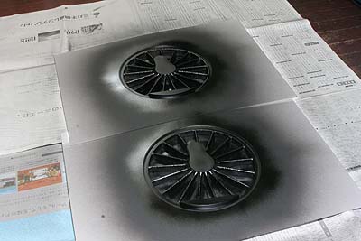
Masking with paper, I sprayed urethane aerosol
paint.

Using the wheel turning jig again, rim and
boss are polished. For boss, I employed sand
paper sticked on a flat board. Note the counter
weight is protected with cloth tape.